| <<Previous |
5.11. I2CIN
Control, Address, Var{, Var}I2CIN
Sends
Control and Address out the I2C clock and data lines and puts the byte(s) received into Var.I2CIN
and I2COUT can be used to read and write data to a serial EEPROM with a 2-wire I2C interface such as the Microchip 24LC01B, 24LC02B and similar devices. This allows data to be stored in non-volatile memory so that it can be maintained even after the power is turned off. These commands operate in the I2C master byte read and write modes and may also be used to talk to other devices with an I2C interface like temperature sensors and A/D converters.The lower 7 bits of the
Control byte contain the control code along with chip select or additional address information, depending on the particular device. The high order bit is a flag indicating whether the following Address is to be sent as an 8 bit or 16 bit address. If this flag is low, the Address is sent as 8 bits. The control code for a serial EEPROM is %1010.For example, when communicating with a 24LC01B, the
Address required is 8 bits, the control code is %1010 and the chip select is unused so the Control byte would be %01010000 or $50. Formats of Control bytes for some of the different parts follow:|
Device |
Capacity |
Control |
Address size |
|
24LC01B |
128 bytes |
%01010xxx |
8 bits |
|
24LC02B |
256 bytes |
%01010xxx |
8 bits |
|
24LC04B |
512 bytes |
%01010xxb |
8 bits |
|
24LC08B |
1K bytes |
%01010xbb |
8 bits |
|
24LC16B |
2K bytes |
%01010bbb |
8 bits |
|
24LC32B |
4K bytes |
%11010ddd |
16 bits |
|
24LC65 |
8K bytes |
%11010ddd |
16 bits |
bbb = block select (high order address) bits
ddd = device select bits
xxx = don't care
See the Microchip Non-Volatile Memory Products Data Book for more information on these and other devices that may be used with the
I2CIN and I2COUT commands.The I2C data and clock lines are predefined in the main library as PortA.0 and PortA.1 respectively. This gets them out of the way of the PortB pins and makes it unnecessary to define them in each
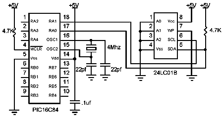
I2CIN or I2COUT statement. They may be assigned to different pins by simply changing the equates at the beginning of the I2C routines in the file PBL.INC.The I2C data line should be pulled up to Vcc with a 4.7K resistor per the following schematic as it is run in a bi-directional open-collector manner.
Symbol con = %01010000 Symbol addr = B5 addr = 17 ' Set address to 17 I2Cin con,addr,B2 ' Read data at address 17 into B2
5.12. I2COUT
Control, Address, ( Value{, Value })I2COUT
I2COUT sends Control and Address out the I2C clock and data lines followed by Value.
When writing to a serial EEPROM it is necessary to wait 10ms (device dependent) for the write to complete before attempting communication with the device again. If a subsequent
I2CIN or I2COUT is attempted before the write is complete, the access will be ignored.While a single
I2COUT statement may be used to write multiple bytes at once, doing so would violate the above write timing requirement for serial EEPROMs. The multiple byte write feature may be useful with I2C devices other than serial EEPROMs that don't have to wait between writes.See the
I2CIN command above for the rest of the story.
Symbol con = %01010000 Symbol addr = B5 addr = 17 ' Set address to 17 I2Cout con,addr,(56) ' Send the byte 56 to address 17 Pause 10 ' Wait 10ms for write to complete addr = 127 ' Set address to 127 I2Cout con,addr,(B12) ' Send the byte in B12 to address 127 Pause 10 ' Wait 10ms for write to complete
| <<Previous |