| <<Previous |
SHIFTIN
DataPin,ClockPin,Mode,[Var{\Bits}...]SHIFTIN
Clock
ClockPin, synchronously shift in bits on DataPin and store the byte(s) received into Var. ClockPin and DataPin may be a constant, 0-15, or a variable that contains a number 0-15 (e.g. B0) or a pin name (e.g. PORTA.0).\Bits optionally specifies the number of bits to be shifted in. If it is not specified, 8 bits are shifted in, independent of the variable type. The Bits shifted in are always the low order bits, regardless of the Mode used, LSB or MSB.
The
Mode names (e.g. MSBPRE) are defined in the file MODEDEFS.BAS. To use them, add the line:"modedefs.bas"Include
to the top of the PICBASIC PRO™ program.
BS1DEFS.BAS and BS2DEFS.BAS already includes MODEDEFS.BAS. Do not include it again if one of these files is already included. The Mode numbers may be used without including this file.. Some Modes do not have a name.For
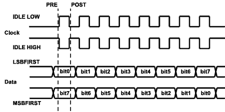
Modes 0-3, the clock idles low, toggles high to clock in a bit, and then returns low. For Modes 4-7, the clock idles high, toggles low to clock in a bit, and then returns high.|
Mode |
Mode No. |
Operation |
|
MSBPRE |
0 |
Shift data in highest bit first, Read data before sending clock. Clock idles low. |
|
LSBPRE |
1 |
Shift data in lowest bit first, Read data before sending clock. Clock idles low. |
|
MSBPOST |
2 |
Shift data in highest bit first, Read data after sending clock. Clock idles low. |
|
LSBPOST |
3 |
Shift data in lowest bit first, Read data after sending clock. Clock idles low. |
|
|
4 |
Shift data in highest bit first, Read data before sending clock. Clock idles high. |
|
|
5 |
Shift data in lowest bit first, Read data before sending clock. Clock idles high. |
|
|
6 |
Shift data in highest bit first, Read data after sending clock. Clock idles high. |
|
|
7 |
Shift data in lowest bit first, Read data after sending clock. Clock idles high. |
The shift clock runs at about 50KHz dependent on the oscillator. The active state is held to a minimum of 2 microseconds. A
DEFINE allows the active state of the clock to be extended by an additional number of microseconds up to 65,535 (65.535 milliseconds) to slow the clock rate. The minimum additional delay is defined by the PAUSEUS timing. See its section for the minimum for any given oscillator. This DEFINE is not available on 12-bit core PICmicro MCUs.For example, to slow the clock by an additional 100 microseconds:
DEFINE SHIFT_PAUSEUS 100
The following diagram shows the relationship of the clock to the data for
the various modes:
SHIFTIN
0,1,MSBPRE,[B0,B1\4]
DataPin,ClockPin,Mode,[Var{\Bits}...]SHIFTOUT
Synchronously shift out
Var on ClockPin and DataPin. ClockPin and DataPin may be a constant, 0-15, or a variable that contains a number 0-15 (e.g. B0) or a pin name (e.g. PORTA.0).\Bits optionally specifies the number of bits to be shifted out. If it is not specified, 8 bits are shifted out, independent of the variable type. The Bits shifted out are always the low order bits, regardless of the Mode used, LSB or MSB. Up to 16 Bits can be shifted out of a single variable. If more than 16 Bits are required, multiple variables or constants may be included between the square brackets.
The
Mode names (e.g. LSBFIRST) are defined in the file MODEDEFS.BAS. To use them, add the line:Include
Amodedefs.bas@to the top of the PICBASIC PRO™ program.
BS1DEFS.BAS and BS2DEFS.BAS already includes MODEDEFS.BAS. Do not include it again if one of these files is already included. The Mode numbers may be used without including this file. Some Modes do not have a name.For
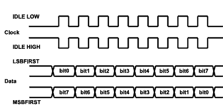
Modes 0-1, the clock idles low, toggles high to clock in a bit, and then returns low. For Modes 4-5, the clock idles high, toggles low to clock in a bit, and then returns high.|
Mode |
Mode No. |
Operation |
|
LSBFIRST |
0 |
Shift data out lowest bit first. Clock idles low. |
|
MSBFIRST |
1 |
Shift data out highest bit first. Clock idles low. |
|
|
4 |
Shift data out lowest bit first. Clock idles high. |
|
|
5 |
Shift data out highest bit first. Clock idles high. |
The shift clock runs at about 50KHz dependent on the oscillator. The active state is held to a minimum of 2 microseconds. A
DEFINE allows the active state of the clock to be extended by an additional number of microseconds up to 65,535 (65.535 milliseconds) to slow the clock rate. The minimum additional delay is defined by the PAUSEUS timing. See its section for the minimum for any given oscillator. This DEFINE is not available on 12-bit core PICmicro MCUs.For example, to slow the clock by an additional 100 microseconds:
DEFINE SHIFT_PAUSEUS 100
The following diagram shows the relationship of the clock to the data for
the various modes:
0,1,MSBFIRST,[B0,B1]SHIFTOUT
PeriodSLEEP
Place microcontroller into low power mode for
Period seconds. Period is 16-bits, so delays can be up to 65,535 seconds (just over 18 hours).SLEEP
uses the Watchdog Timer so it is independent of the actual oscillator frequency. The granularity is about 2.3 seconds and may vary based on device specifics and temperature. This variance is unlike the BASIC Stamp. The change was necessitated because when the PICmicro executes a Watchdog Timer reset, it resets many of the internal registers to predefined values. These values may differ greatly from what your program may expect. By running the SLEEP command uncalibrated, this issue is sidestepped.SLEEP 60 ' Sleep for about 1 minute
Pin,[Note,Duration{,Note,Duration...}]SOUND
Generates tone and/or white noise on the specified
Pin. Pin is automatically made an output. Pin may be a constant, 0 - 15, or a variable that contains a number 0 - 15 (e.g. B0) or a pin name (e.g. PORTA.0).Note
0 is silence. Notes 1-127 are tones. Notes 128-255 are white noise. Tones and white noises are in ascending order (i.e. 1 and 128 are the lowest frequencies, 127 and 255 are the highest). Note 1 is about 78.74Hz and Note 127 is about 10,000Hz.Duration
is 0-255 and determines how long the Note is played in about 12 millisecond increments. Note and Duration needn't be constants.SOUND
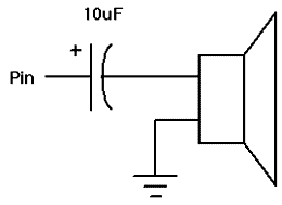
outputs TTL-level square waves. Thanks to the excellent I/O characteristics of the PICmicro, a speaker can be driven through a capacitor. The value of the capacitor should be determined based on the frequencies of interest and the speaker load. Piezo speakers can be driven directly.
SOUND PORTB.7,[100,10,50,10] ' Send 2 sounds consecutively to Pin7
STOP
Stop program execution by executing an endless loop. This does not place the microcontroller into low power mode. The microcontroller is still working as hard as ever. It is just not getting much done.
STOP ' Stop program dead in its tracks
Variable,VariableSWAP
Exchange the values between 2 variables. Usually, it is a tedious process to swap the value of 2 variables.
SWAP does it in one statement without using any intermediate variables. It can be used with bit, byte and word variables. Array variables with a variable index may not be used in SWAP although array variables with a constant index are allowed.temp = B0 ' Old way B0 = B1 B1 = temp SWAP B0, B1 ' New way
| <<Previous |